Voertuiggegevens:
| Chassisnummer | W0L6ZZR1BH9…… |
| Modelcode | 0FB05 |
| Carrosserie | B05 |
| Modeljaar | 2017 (A) |
| Productiedatum | 19-sep-2016 |
| Eerste invoer | 1-dec-2016 |
| Motorcode | LJ5 |
| Motortype | A16FDL |
| Serienummer motor | 7703685 |
| Versnellingcode | MMJ |
| Kleurencode | 5PU |
| Stofferingscode | TAIC |
| Pakketcode | I3I1 |
Klachtomschrijving:
Storing turbo actuator.
De actuator is reeds vervangen.
Foutcode is anders dan voor vervangen, maar er blijft een code m.b.t. de verstelling van de
turbo terugkeren.
De oorspronkelijke code was P0046, de code die nu verschijnt is P2563.
In eerste instantie naar DSN voor inleren turbo actuator. Het inleren van de actuator is niet
succesvol.
Voertuigscan:
Inspuiting Diesel Bosch EDC17C49 CF5/5+ EOBD CAN (EP mot. 1.6/2.0)
DTC Beschrijving
P2563-22 Stand turbo met variabele geometrie, Aanwezig
Diagnose:
De oorspronkelijke foutcode heeft betrekking op het actuatorcircuit zelf:
DTC P0046 Condition 1
Control Circuit = Short between the circuits
Condition 2
Turbocharger Vane Position Actuator High Current.
De nu aanwezige foutcode, P2563, heeft betrekking op de positie van de turbo actuator.
Foutcode P2563 blijft herhaaldelijk terugkeren en de inleerprocedure is niet succesvol:
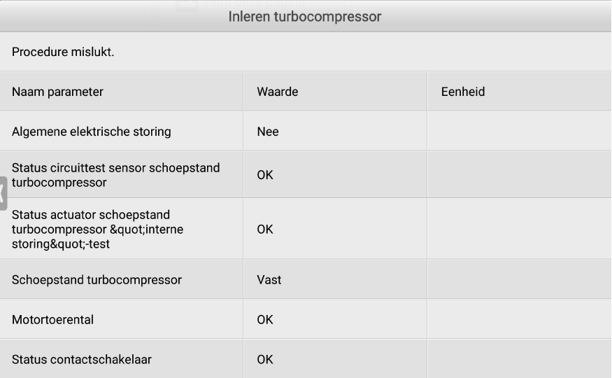
De turbo reageert niet op een actuatortest.
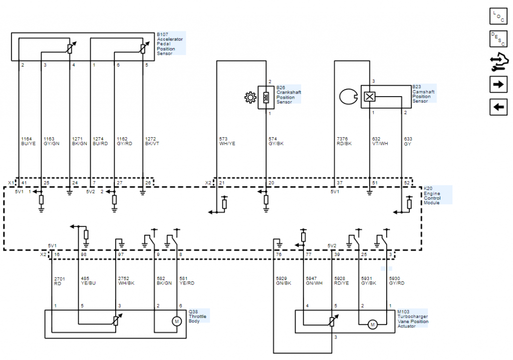
We gaan eerst het circuit controleren aan de hand van onderstaande schema en de diagnose handleiding van de fabrikant. De geel gemarkeerde delen geven het verloop van de test aan, de rode tekst zijn toegevoegde opmerkingen:
DTC P2563
- Perform the Diagnostic System Check prior to using this diagnostic procedure: Diagnostic System Check – Vehicle
- Review the description of Strategy Based Diagnosis: Strategy Based Diagnosis
- An overview of each diagnostic category can be found here: Diagnostic Procedure Instructions
DTC P2563
Turbocharger Vane Position Sensor
Symptom Byte Information:
- Symptom Byte: 21 – Low Signal Amplitude
- Symptom Byte: 22 – High Signal Amplitude
| Circuit | Short to Ground | Open/High Resistance | Short to Voltage | Signal Performance |
|---|---|---|---|---|
| 5 V Reference | P0641 | P2562 | P0641 | — |
| Signal | P2562 | P2562 | P2562 | P2563 |
| Low Reference | — | P2562 | — | — |
| Circuit | Description |
|---|---|
| 5 V Reference | Regulated voltage supplied by the control module. |
| Signal | The control module input circuit has an internal resistance connected to 5 V. (ik meet geen 5 volt vanuit ecu bij losgenomen stekker). |
| Ground | Grounded through the control module. |
| Component | Description |
|---|---|
| B112 Turbocharger Vane Position Sensor | The sensor is an analog potentiometer that varies its resistance proportionally with the position of the control rod. |
| K20 Engine Control Module | The control module controls a series of actuators to ensure optimal engine performance. The control module does this by reading values from a variety of sensors, interprets the data and adjusts the engine actuators accordingly. |
The variable geometry turbocharger includes a ring of aerodynamically shaped vanes in the turbine housing at the exhaust inlet. With changing the angle of the vanes it is possible to regulate the boost pressure. The vanes are rotated by a vacuum actuator which is controlled by a solenoid valve.
Conditions for Running the DTC
Condition 1
Ignition = On
Condition 2
Engine = Running
Conditions for Setting the DTC
P2563 21
Turbocharger Vane Position Sensor = Out Of Range — More open than desired
P2563 22
Turbocharger Vane Position Sensor = Out Of Range — More closed than desired
Actions Taken When the DTC Sets
DTC P2563 is a Type A DTC.
Conditions for Clearing the DTC
DTC P2563 is a Type A DTC.
Schematic Reference
Connector End View Reference
Electrical Information Reference
- Circuit Testing
- Connector Repairs
- Testing for Intermittent Conditions and Poor Connections
- Wiring Repairs
DTC Type Reference
Powertrain Diagnostic Trouble Code (DTC) Type Definitions
Scan Tool Reference
- Ignition » On / Vehicle » In Service Mode
- Verify DTC P0641 is not set.
- If the DTC is set
Refer to: Diagnostic Trouble Code (DTC) List – Vehicle
- If the DTC is not set
- Perform the scan tool control function: Turbocharger Vane Position Actuator
Verify the scan tool procedure was successful.
- If the scan tool procedure was not successful
Refer to: Circuit/System Testing
- If the scan tool procedure was successful
- Operate the vehicle within the Conditions for Running the DTC. You may also operate the vehicle within the conditions that you observed from the Freeze Frame/Failure Records data.
- Verify the DTC does not set.
- If the DTC sets
Refer to: Circuit/System Testing
- If the DTC does not set
- All OK.
- Ignition/Vehicle » Off
- Verify the condition does not exist:
- Mechanically damaged turbocharger.
- Mechanically stuck turbocharger vane position control.
- If a condition exists
Repair or replace as necessary.
- If no condition exists
- Disconnect the electrical connector: M103 Turbocharger Vane Position Actuator
Note : It may take up to 2 min for all vehicle systems to power down before an accurate ground or low reference circuit continuity test can be performed.
- Test for less than 5 Ω between the test points: Low Reference circuit terminal 3 & Ground
- If 5 Ω or greater
- Ignition/Vehicle » Off
- Disconnect the electrical connector: X2 @ K20 Engine Control Module
- Test for less than 2 Ω between the test points: Low Reference circuit terminal 3 @ Component harness & Terminal 76 @ Control module harness
- If 2 Ω or greater » Repair the open/high resistance in the circuit.
- If less than 2 Ω » Replace the component: K20 Engine Control Module
- If less than 5 Ω
- Ignition » On / Vehicle » In Service Mode
- Test for 4,8 to 5,2 V between the test points: 5 V Reference circuit terminal 5 & Low Reference circuit terminal 3
- If less than 4,8 V
- Ignition/Vehicle » Off
- Disconnect the electrical connector: X2 @ K20 Engine Control Module
- Test for infinite resistance between the test points: 5 V Reference circuit terminal 5 @ Component harness & Ground
- If less than infinite resistance » Repair the short to ground on the circuit.
- If infinite resistance
- Test for less than 2 Ω between the test points: 5 V Reference circuit terminal 5 @ Component harness & Terminal 39 @ Control module harness
- If 2 Ω or greater » Repair the open/high resistance in the circuit.
- If less than 2 Ω » Replace the component: K20 Engine Control Module
- If greater than 5,2 V
- Ignition/Vehicle » Off
- Disconnect the electrical connector: X2 @ K20 Engine Control Module
- Test for less than 1 V between the test points: 5 V Reference circuit terminal 5 @ Component harness & Ground
- If 1 V or greater » Repair the short to voltage on the circuit.
- If less than 1 V » Replace the component: K20 Engine Control Module
- If between 4,8 and 5,2 V
- Ignition/Vehicle » Off
- Disconnect the electrical connector: X2 @ K20 Engine Control Module
- Test for infinite resistance between the test points: Signal circuit terminal 4 @ Component harness & Ground
- If less than infinite resistance
Repair the short to ground on the circuit.
- If infinite resistance
- Test for less than 2 Ω between the test points: Signal circuit terminal 4 @ Component harness & Terminal 77 @ Control module harness
- If greater than 2 Ω
Repair the open/high resistance in the circuit.
- If less than 2 Ω
- Ignition » On / Vehicle » In Service Mode
- Test for less than 1 V between the test points: Signal circuit terminal 4 @ Component harness & Ground
- If greater than 1 V
Repair the short to voltage on the circuit.
- If less than 1 V
- Replace the component: M103 Turbocharger Vane Position Actuator (is vervangen)
- Operate the vehicle within the Conditions for Running the DTC. You may also operate the vehicle within the conditions that you observed from the Freeze Frame/Failure Records data.
- Verify the DTC does not set.
- If the DTC sets
Replace the component: K20 Engine Control Module
- If the DTC does not set
- All OK.
Uit ervaring weten we dat de test handleidingen van de fabrikant vaak tekort schieten. Ook in dit geval lijkt het ons verstandig om nog een aantal controles uit te voeren.
Als toevoeging op bovenstaande teststappen hebben we de signaaldraad belast gecontroleerd, deze is in orde.
Op de draad staat 0,3 volt bij aangesloten stekker en 0 volt bij losgenomen stekker, er staat dus geen
5 volt op vanuit de motor ecu, wat in mijn optiek wel zou moeten aangezien aangegeven wordt dat
de signaaldraad intern via een weerstand aan 5 volt is gelegd.
Zowel de teststappen van de fabrikant als het feit dat er geen 5 volt op de signaaldraad staat wijzen
in de richting van een defecte ecu.
Omdat de auto echter binnen was gekomen met een andere foutcode is het onwaarschijnlijk dat nu
ineens de ecu defect is.
In live data is in de parameters geen positie van de actuator uit te lezen. Als we een actuatortest
doen, dan zien we de positie wel erbij staan in procenten, deze staat dan op -20%.
We testen of we het signaal kunnen beïnvloeden door de signaaldraad via een led te verbinden met
de voeding. Daarop gaat de signaalspanning omhoog en de actuator beweegt.
De ecu doet dus wel wat met de input van het signaal.
Hierna lukt het ook om de actuator in te leren. Wel is na het inleren een foutcode aanwezig, maar
deze kunnen we wissen en de foutcode keert niet terug.
Wel valt op dat de actuator nu vast staat in een positie van 100% (signaalspanning 4 volt).
De ecu blijft foutvrij, ook nadat deze in rust is geweest en bij lopende motor, maar de positie van de
turbo wijzigt nooit.
Als we een actuatortest doen zien we een gewenste positie van 85%, een gemeten positie van 100%
en een aansturing die constant varieert tussen 0 en 100%. Dit hoor je ook terug in de actuator, maar
deze beweegt niet.
Ondanks het feit dat er geen foutcodes worden opgeslagen, is dit niet in orde.
We meten de stroom door de actuator t.o.v. het positie signaal:
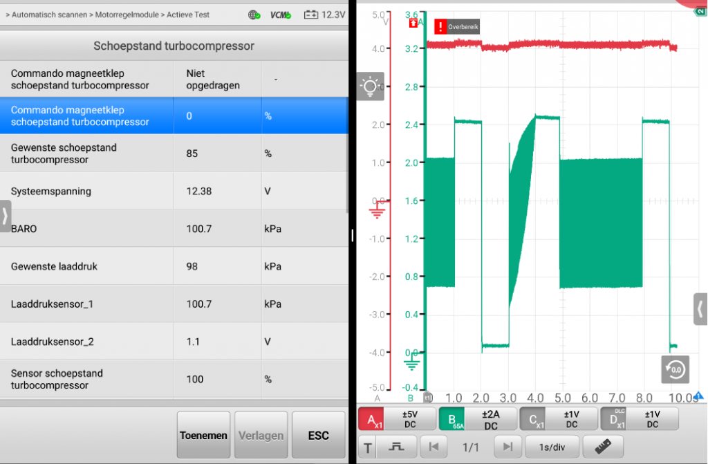
Links de actuatortest, Hierbij reageert de actuator niet op een eventueel opgedragen commando,
maar we zien wel de aansturing en feedback in procenten.
Rechts het scoopbeeld met in het rood de signaalspanning en in het groen de stroomopname van de
actuator.
Wat opvalt, de actuator trekt 2,4 amphere stroom en op dat moment zien we de signaalspanning nog
iets verhogen. In feite staat de actuator dus al tegen de eindaanslag, maar probeert de ecu deze nog
verder aan te sturen.
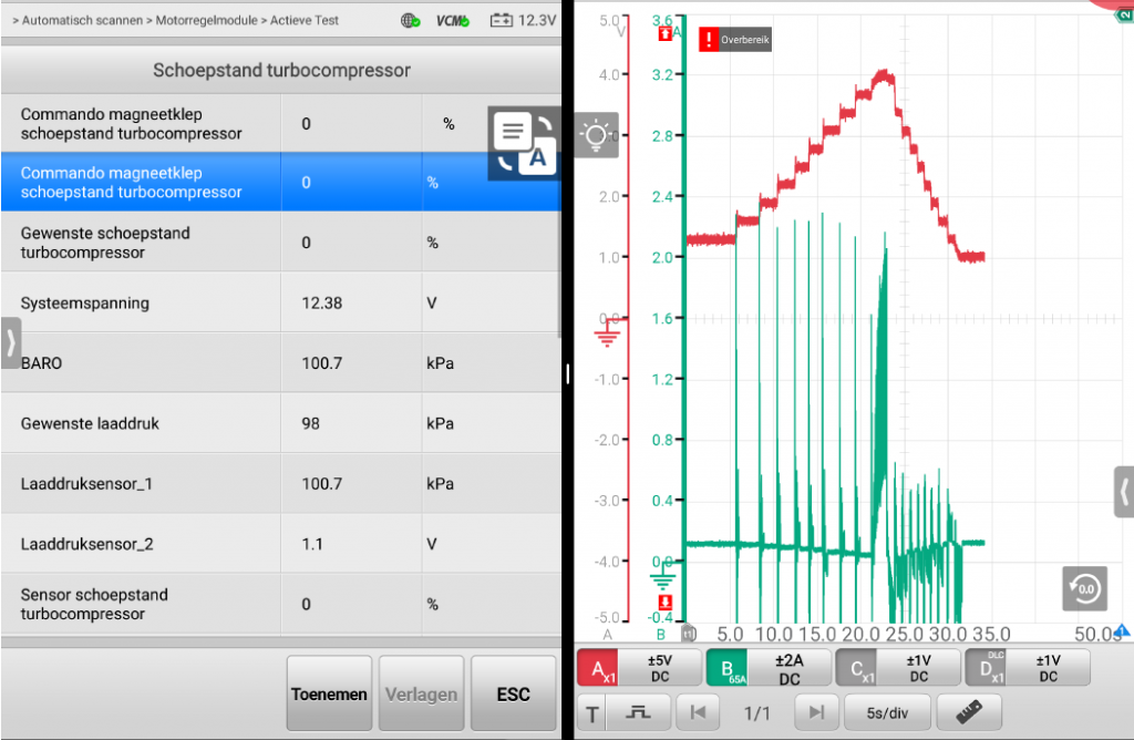
We gaan even een paar stappen terug, in eerste instantie stond de actuator constant in de andere
eindpositie en was de signaalspanning 0,3 volt.
Dit is veranderd toen we de signaalspanning omhoog trokken door deze via een led te verbinden met
de voeding. De ecu ging daarop de actuator andersom aansturen waardoor de andere eindstand is
bereikt, om vervolgens vast in deze stand te staan.
Dit zou kunnen ontstaan als de + en – van de actuator zijn omgedraaid, de ecu zal dan de actuator in
de tegengestelde richting sturen ten opzichte van de gewenste positie.
We sluiten de actuator aan via break out kabels en wisselen hierbij de 2 stuurdraden om.
Hierna voeren we opnieuw de inleerfunctie uit.
Deze verloopt succesvol.
Opnieuw doen we de actuatortest, nu zien we dat de actuator correct reageert op het opgegeven
commando:
Conclusie:
De bedrading zit nog op de oorspronkelijke posities, hier is niets gewisseld.
Deze actuator is geleverd door een bedrijf wat gespecialiseerd is in turbo’s, origineel is deze actuator niet los verkrijgbaar. Volgens alle beschikbare informatie zou deze actuator echter wel geschikt moeten zijn voor deze auto. Uit onze diagnose blijkt echter dat deze actuator niet geschikt is voor deze auto, de + en – zitten verkeerd om.
In overleg met de opdrachtgever lossen we dit op door de positie van de stuurdraden te wisselen in de stekker die op de actuator komt. Hierna maken we een uitgebreide proefrit. De auto trekt goed en er keren geen foutcodes meer terug.